As we now know that for an object to be rendered, we must have a ray intersecting with that object and the reflection point on that object where the intersection occurred redirect the ray towards a light source. As ray tracing algorithms go, the sphere object is the easiest to deal with as other objects such as polygons, need more complex algorithms.
Of all the steps needed to render an image, one equation stands above the rest, the ray equation:
A ray equation defines a ray as:
R(t) = R0 + Rd * t where t > 0
Linear Algebra: Normalized Vectors
The ray equation works with any value of t, but the normalization process enables us to calculate the distance of a specified point on the ray in world units, as a normalized vector has the length of 1. The conversion of a given vector to a normalized one is a simple task; once the Euclidean length of a vector is known, each x, y, z component is divided by the vector's length. The result is a vector going in the same direction as the original, but with a length of 1. When applied to our ray equation, the normalization process makes calculations easier. We could, for example have a ray starting at the world origin [0,0,0] with a normalized direction vector of [1,1,1] a t value of 2 would yield a R(2) = [2,2,2].
Simple Ray tracer: useful method:
Since vector normalization is a common vector conversion, it would be useful if a java method would be implemented to serve this simple purpose; here is the normalise_vector method, a member of the RayTracer class. It inputs a vector and returns a normalized version.
public double[] normalise_vector(double[] v){
double length = 0.0;
double[] v_norm = new double[3];
for(int i = 0 ; i < 3 ; i++)
length = length + Math.pow((v[i]), 2);
length = Math.sqrt(length);
for(int i = 0 ; i < 3 ; i++)
v_norm[i] = ((v[i])) / length;
return v_norm;}
Ray / Sphere Intersection: Process
The rendering process involves basically two elements: firstly, if a ray collides with an object at a specific coordinate, and secondly, if such a coordinate exists, finding the appropriate light intensity at that point to give back to the corresponding imagebuffer pixel. We can summarize these steps:
The rendering process involves basically two elements: firstly, if a ray collides with an object at a specific coordinate, and secondly, if such a coordinate exists, finding the appropriate light intensity at that point to give back to the corresponding imagebuffer pixel. We can summarize these steps:
- Find the appropriate direction vector for the ray equation
- Find if a collision occurs with the object
- If a collision occurs, find the world coordinates of the point of collision
- Find the normal vector at that point
- Apply the Phong shading algorithm to that point
- Return the found light intensity to image pixel
Find the appropriate direction vector for the ray equation
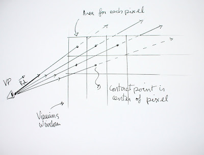
The direction vector needed to qualify our ray is found by subtracting the viewpoint from a coordinate inscribed in viewing window plane . Since we have to do this operation for every pixel in the image, this calculation is easily implement using a double image width / image height loop. The ray tracer's ViewPoint class uses the create_unit_vector method which finds the precise coordinate of where the pixel's center would be in the viewing window, by dividing the area of the window by the number of pixels in the image. By using coordinate offsets, the coordinates of the center of each square area is used for finding the unit vector for that particular pixel. Since the viewing window is an abstract concept, we can potentially change the number of rays that can go through the window by changing the values of the offsets. We will use this technique when dealing with the antialising issue further ahead.
It is useful to note that the create_unit_vector method returns our ray vector under a normalized form. This, once again, simplifies evaluating if results are appropriate as they are represented in world units.
Find if a collision occurs with the object
Now that we have established a normalized direction vector, the next step would be to verify if, for a particular ray, a collision occurs with a specific object. It is interesting to note that each type of primitive object (polygon, sphere, cone, etc...) will have different formulas for calculating the intersection with the ray.
The ray / sphere intersection is found by a combination of the ray's equation with the sphere's implicit equation we described earlier. We can then express this equation in terms of t. Since the complete details of this substitution can be found in Glassner's book (pp 36-37), we will just focus on the more general aspects of finding this t value and the interpretation of its value.
The substitution of the ray equation in the sphere's equation will yield, in terms of t, an equation of the form A* t2 + b*t + C = 0 a quadratic equation. The values of A, B and C, are easily found from elements we already possess like, the point of origin of the ray, the normalized vector, the center coordinates of the sphere. Once again, the detailed equations can be found in Glassner (pp 36-37).
Being a quadratic equation, t will have 2 potential values; But It is important to notice beforehand that if the discriminant of the quadratic equation is negative this ray misses the sphere entirely, and no further computation are necessary for this particular ray. If the discriminant is positive, then a collision has occurred. It is easy to implement a Boolean value that verifies this.
A positive discriminant will create two t values: These t values can either positive or negative. Only positive t values will be examined as they represent the distance in world units from the viewpoint to the intersection point. If 2 positive t values are found, only the smallest one should be considered to find the point of intersection as it is the one closest to viewpoint, therefore the only visible one if our object is not translucent.
A quick summary of values:
The direction vector needed to qualify our ray is found by subtracting the viewpoint from a coordinate inscribed in viewing window plane . Since we have to do this operation for every pixel in the image, this calculation is easily implement using a double image width / image height loop. The ray tracer's ViewPoint class uses the create_unit_vector method which finds the precise coordinate of where the pixel's center would be in the viewing window, by dividing the area of the window by the number of pixels in the image. By using coordinate offsets, the coordinates of the center of each square area is used for finding the unit vector for that particular pixel. Since the viewing window is an abstract concept, we can potentially change the number of rays that can go through the window by changing the values of the offsets. We will use this technique when dealing with the antialising issue further ahead.
 |
| Direction vector for each pixel. Viewing window is divided into areas corresponding to each pixel in the image ( Illustration by Martin Bertrand) |
It is useful to note that the create_unit_vector method returns our ray vector under a normalized form. This, once again, simplifies evaluating if results are appropriate as they are represented in world units.
Find if a collision occurs with the object
Now that we have established a normalized direction vector, the next step would be to verify if, for a particular ray, a collision occurs with a specific object. It is interesting to note that each type of primitive object (polygon, sphere, cone, etc...) will have different formulas for calculating the intersection with the ray.
The ray / sphere intersection is found by a combination of the ray's equation with the sphere's implicit equation we described earlier. We can then express this equation in terms of t. Since the complete details of this substitution can be found in Glassner's book (pp 36-37), we will just focus on the more general aspects of finding this t value and the interpretation of its value.
The substitution of the ray equation in the sphere's equation will yield, in terms of t, an equation of the form A* t2 + b*t + C = 0 a quadratic equation. The values of A, B and C, are easily found from elements we already possess like, the point of origin of the ray, the normalized vector, the center coordinates of the sphere. Once again, the detailed equations can be found in Glassner (pp 36-37).
Being a quadratic equation, t will have 2 potential values; But It is important to notice beforehand that if the discriminant of the quadratic equation is negative this ray misses the sphere entirely, and no further computation are necessary for this particular ray. If the discriminant is positive, then a collision has occurred. It is easy to implement a Boolean value that verifies this.
A positive discriminant will create two t values: These t values can either positive or negative. Only positive t values will be examined as they represent the distance in world units from the viewpoint to the intersection point. If 2 positive t values are found, only the smallest one should be considered to find the point of intersection as it is the one closest to viewpoint, therefore the only visible one if our object is not translucent.
A quick summary of values:
- If discriminant is negative - no collision has occurred
- If t value negative, disregard, as intersection point with object is behind viewpoint
- Smallest positive t value is chosen to find intersection coordinate
If a collision occurs, find the world coordinates of the point of collision
To find the actual coordinate of the point where the ray intersects is simple. It is inserted in our first ray equation. This is in fact also another useful method of the RayTracer class called get_intersection_point. It inputs a viewpoint (acting as ray origin) a unit direction vector, and the t value. It will return the coordinates of the point a distance of t from the origin.
public double[] get_intersection_point(double[] vp, double[] unit_vector, double t){
double[] intersection = new double[3];
for(int i = 0 ; i < 3 ; i++)
intersection[i] = vp[i] + unit_vector[i] * t;
return intersection;
}
This will yield the intersection's coordinate for our particular ray and pixel. The next step would be calculate the light intensity at that particular point. To give our sphere the appearance of a 3-D volume, we will use the Phong shading algorithm at that point. We will describe this algorithm in the next section.
Implementation test
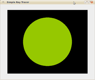
At this level, it would be useful to test if our ray / sphere intersection works properly. One simple way of doing so would be that if a ray sphere collision is detected, return a single fixed intensity value to the image buffer at the specified pixel. If the algorithm is successful, one should see a flat circle of uniform colour.
 |
| Successful Ray / Sphere intersection. Here, a single colour value is given to all pixels. |
